Ceramic Forum, Glass Manufacturing Technology and Wide-Gap Semiconductors
Capacitance Transient Measurement
In DLTS method, the basic method is to perform capacitance transient measurement at each temperature while continuously changing the sample temperature.
The measuring method of the capacitance transient waveform in the DLTS measurement is shown in Figures A-2 and A-3.
Figure A-2 (a) shows the voltage application sequence (① - ③) in transient measurement. Figure A-2 (b) shows the corresponding changes in junction capacitance.
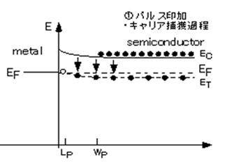
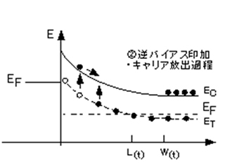
Also, in Figure A-3, the band profile near the sample electrode at each stage of the sequence is shown.
Figure A-2 (a) Bias voltage sequence in capacitance transient measurement and (b) junction capacitance change in corresponding sample
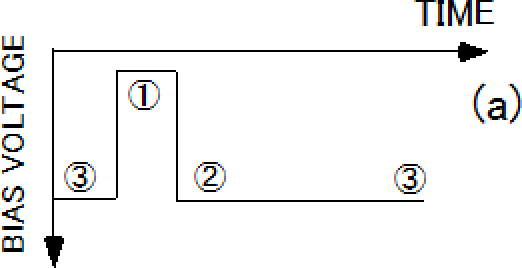
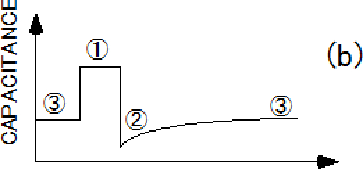
Figure A-3 Band profile at each stage of Figure A-2
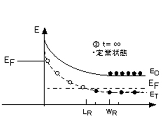
(③)First of all, a reverse bias voltage is applied to the sample.
(①)When the capture pulse voltage in the forward direction is applied here, the band profile is almost in a flat band state. And, electrons are captured at the electron trap level (ET) which is below the Fermi level (EF) (low energy state).
(②)At the next instant, when the capture pulse application is turned off, electrons are emitted from the trap above the EF into the conduction band.Due to the trap from which electrons are emitted being positively charged, the depletion layer width decreases (= increases of junction capacitance), to cancel the charge.In other words, the process of electron emission is directly reflected in the change in junction capacitance.
(③)After a finite time, the electron emission is completed and the system is in a steady state (junction capacitance is constant).
That is, by monitoring the junction capacitance change (transient) at the stage of ②, it is possible to capture the process of electron emission from the target trap level.
In other words, the time constant of this transient waveform contains information regarding trap parameters (level energy and capture cross-section) and its amplitude includes information regarding trap density.
Therefore, the current DLTS method is to fully collect transient data, and efficiently extract necessary information by using various mathematical methods against this transient data.This point is described in detail below.
When the trap concentration (NT) satisfies the relationship of NT < NS with respect to the shallow donor concentration (NS), the above capacitance transient changes exponentially, and is expressed by the following formula (A-1).

CR: constant capacitance at t=∞, ΔC: total capacitance change (amplitude of transient), τe: thermal emission time constant of electron


Also, λ is the distance from the intersection of the trap level and the Fermi level close to the depletion region. Although it is in the depletion layer, carrier emission from the trap level does not occur (Figure A-3).λ is calculated by the following formula (A-20).

εr: permittivity of vacuum, ε0: relative permittivity of semiconductor q: elementary charge of electrons
If the pulse / bias voltage for transient measurement is chosen to be Lp ≈ 0, λ << WR, the amplitude comes to be approximately ().
